
These step-by-step instructions use simple examples to explain the versatility of SmartWOP construction.
This example will focus primarily on the back panel and the order in which it is placed, but we will also use island holes matched to the shelves and incorporate components from the example gallery.
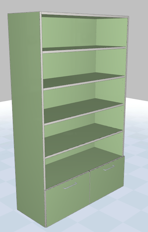
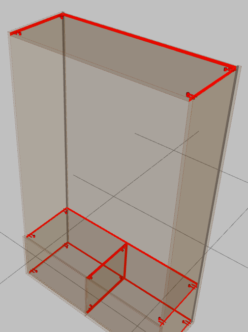
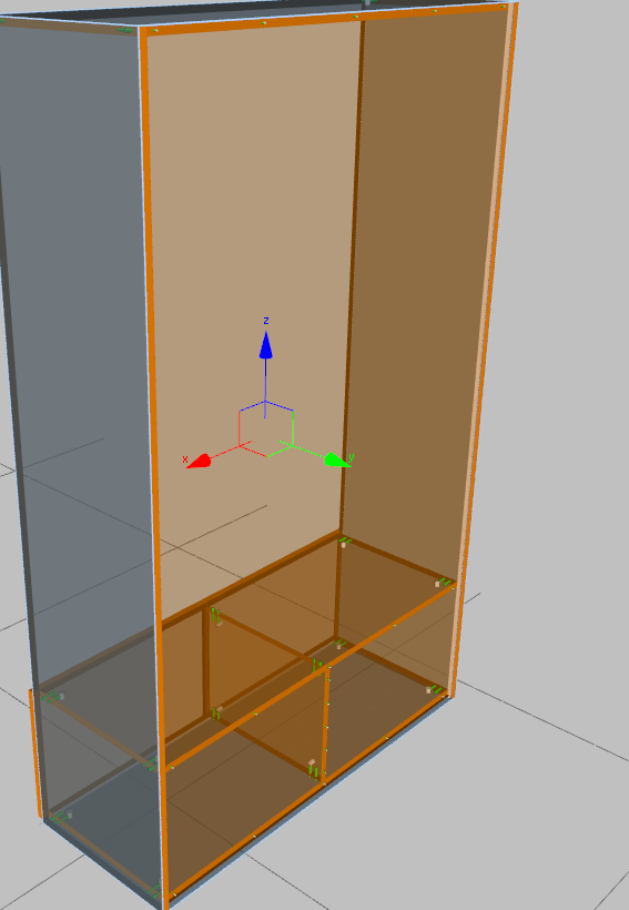
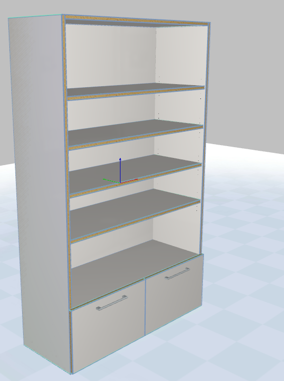
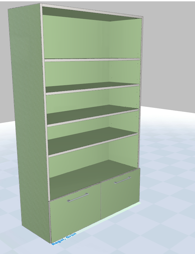
This is our project:
Step 1:
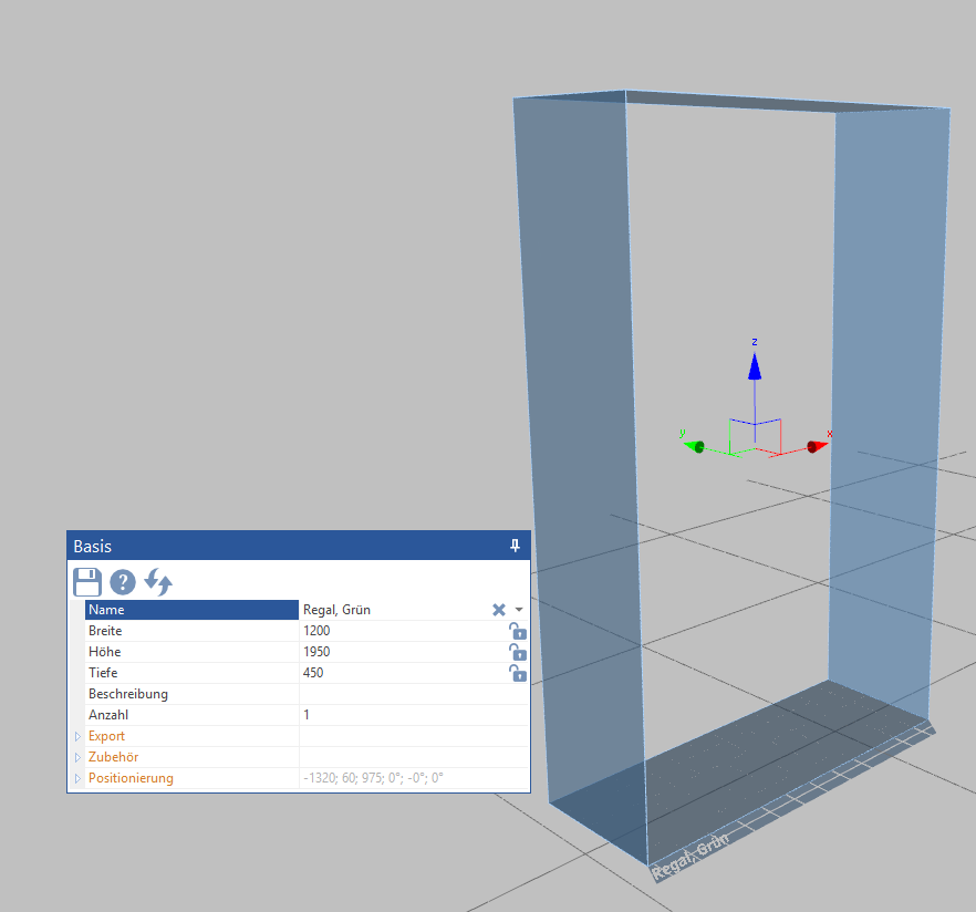
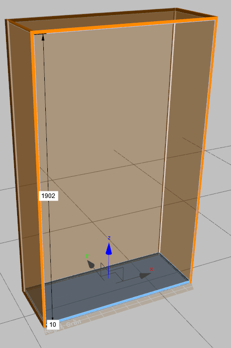
Placing, setting and naming the base
Enter a name for your base and change the dimensions as shown above. Width 1200mm, height 1950mm and depth 450mm.
Step 2:
Indenting and naming the pages
When naming elements, avoid umlauts, special characters and spaces. It may happen that your machine has problems with these characters.
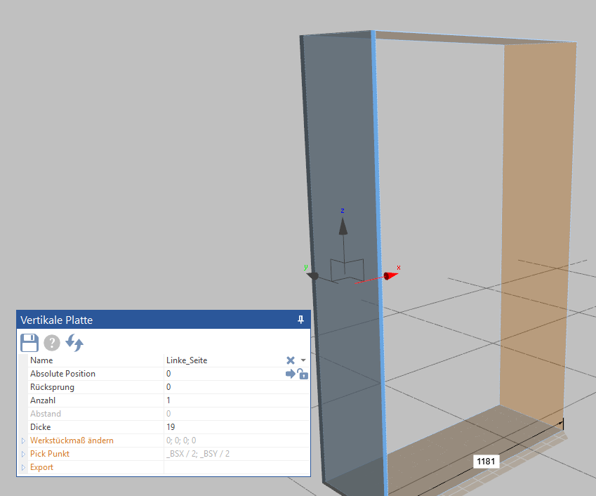
Step 3:
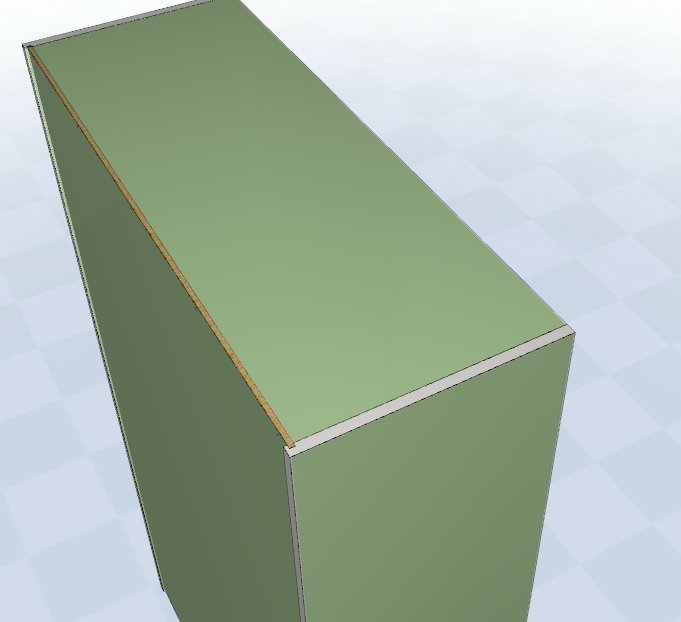
Drawing in and naming the back wall
Simply slide the back panel between the two sides. In this example, the back wall should be 8 mm thick and set back 8 mm from the back edge, resulting in a set back of 16 mm.
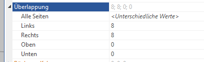
We want the back panel to be slotted 8mm into the side panels. To do this, we need to set the overlap as follows.
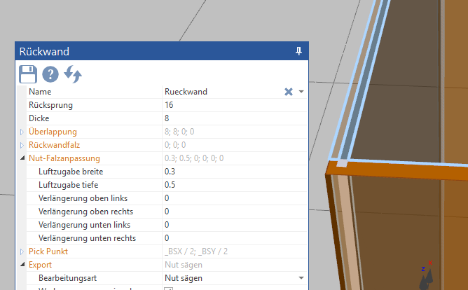
Step 3:
Drawing in and naming the back wall
Simply slide the back panel between the two sides. In this example, the back wall should be 8 mm thick and set back 8 mm from the back edge, resulting in a set back of 16 mm.
We want the back panel to be slotted 8mm into the side panels. To do this, we need to set the overlap as follows.
If your back wall has a small distance from the top or bottom, you can also enter negative values for the overlap at the top and bottom.
We'll neglect the groove fold adjustment for the moment and go straight to the last point that we have to set here first - export.
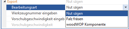
Since we want to groove the back wall and not rabbet it, the Saw groove option must also be selected here.
Step 4:
Draw in and name the base and lid
We raised the floor by 10 mm, but the rear wall is still pulled through to the bottom, which means we have to work on it again. We also want to groove the grooves, so we modify the Groove Fold Adjustment settings.
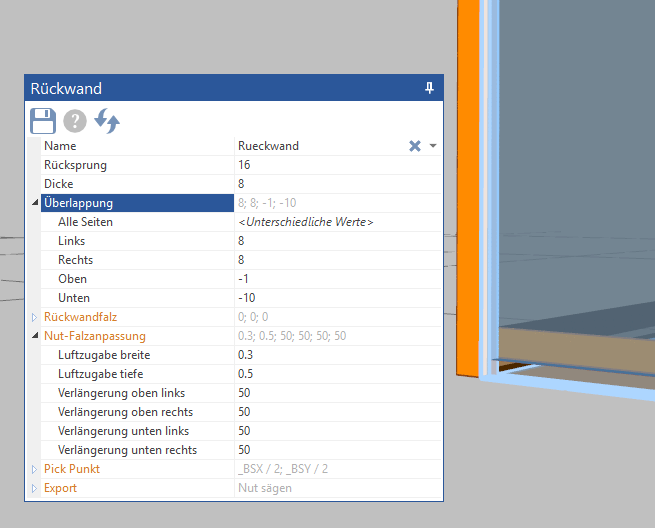
With the negative numbers in the overlapping area, we influence the dimensions of the back wall. The 50 mm extension on all 4 sides ensures continuous grooves.
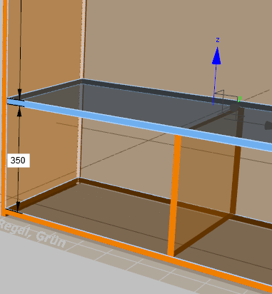
Step 5:
Construction base and drawer fronts
We first pull in the horizontal plate and name it, then the vertical plate in the middle below. In this example, the distance between the two horizontal plates should be 350 mm.
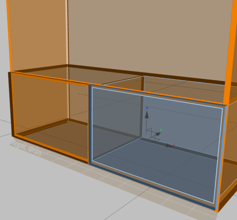
Now the drawer fronts are opened and named.
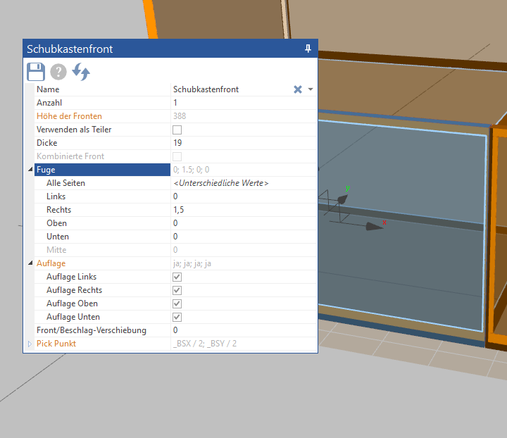
In this example, we want the fronts to be flush with the body at the top, bottom and outside and have a gap of 3 mm in the middle. Double-clicking on a front selects both. We can now set the value for joint “All sides” to 0.
Then we click on the fronts individually and only change the value for the gap in the middle. Correspondingly, the left front has a right gap of 3 mm and the right front has a left gap of 3 mm; SmartWOP now knows that it does not have to form a 6 mm joint but a 3 mm joint.
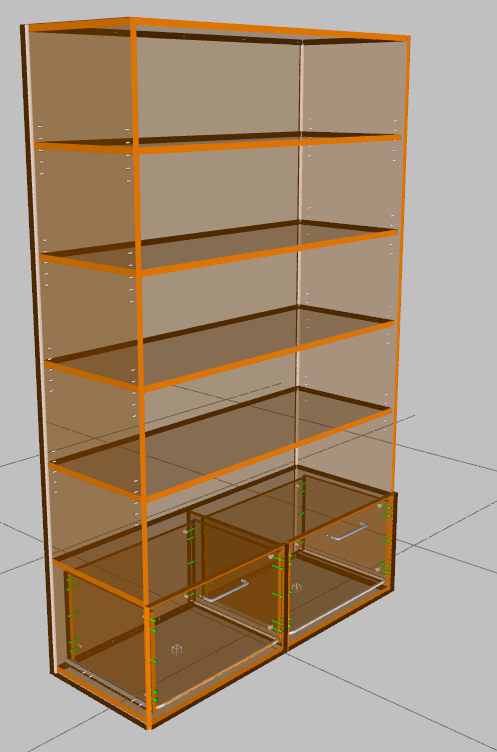
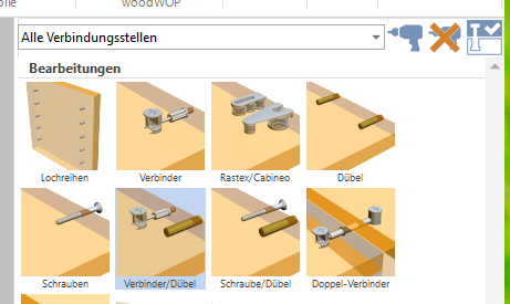
In this example we will connect all the panels with connectors and dowels.
To do this, select “All connection points” in the edit tab at the top right in the selection menu.
It should be noted that possible connections to the rear panel are now also displayed. However, SmartWOP knows that the rear panel is not usually attached with connectors and dowels and leaves this connection free when performing the next step.
A click on the drilling machine symbol with the selected “connector/dowel” ensures that all panels are connected automatically.
Before the screws are pulled in, let's check whether there are any collisions between the connectors.
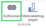
To do this, simply click on the item Collisions in the menu.
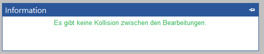
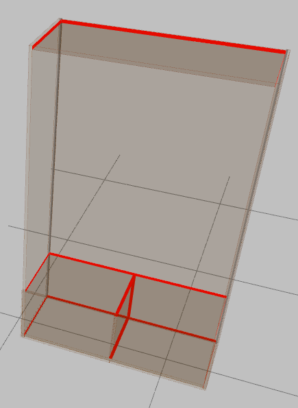
If there are collisions, they are now highlighted with a red frame. If there are no collisions, this message will be displayed.
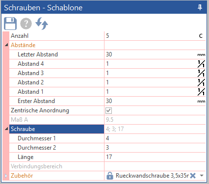
Now let's take care of the back panel screws.
First we set the correct values in the template. Simply click on the screw symbol.
We have already created a rear panel screw here, but of course an existing screw can also be modified. After the settings do not forget to click on the disk symbol to save the settings.
Select “All Connection Points” again. Now, as before, all possible locations are also highlighted, even those that have already been supplied with dowels and connectors.
If you now confirm the entry with the drill, SmartWOP automatically knows that connection points that are already occupied should be ignored and only inserts the screws in the free positions.
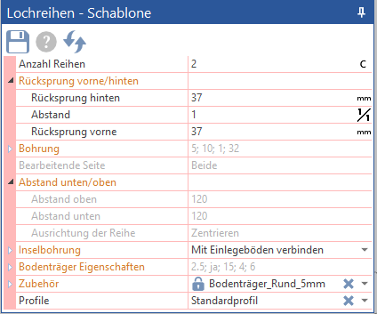
The last step is the row of holes for the shelves. To do this, we go to the editing tab and select the rows of holes in the upper part. As before, we first adjust the template.
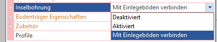
We want island holes that connect to the shelves for this example. In the Island drilling field, you can select how SmartWOP behaves.
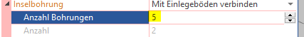
We select Connect to shelves and set the number of holes to 5.
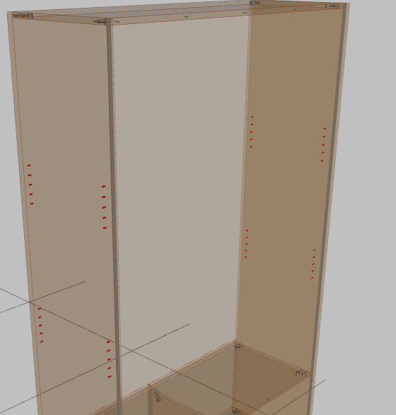
Once this is done, simply drag the rows of holes to the top of our shelf.
Only 2 islands of 5 are shown now, this will change automatically when we put in the shelves.
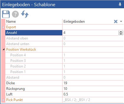
Step 7:
Put in shelves
As always, here we will first set the template and then drag it into the body.
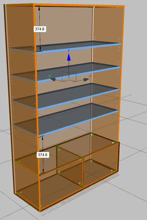
A return of 10 mm is set and the number is increased to 4. If we now pull in these floors, the island drillings will also adapt.
Step 8:
Place extensions and handles
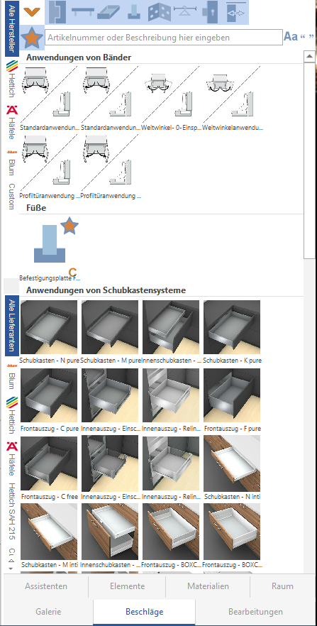
We switch to the Fittings tab.
As a default setting, SmartWOP initially only shows the fittings that have been marked as favorites. But we want to look for a fitting, so we first deactivate the favorites function by clicking on the yellow star. The area previously highlighted in blue becomes white.
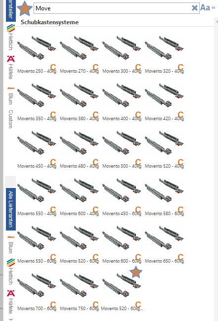
In this example we want to use Movento excerpts. To do this, we first click on the excerpt symbol and can now enter Movento or parts of it in the search mask.
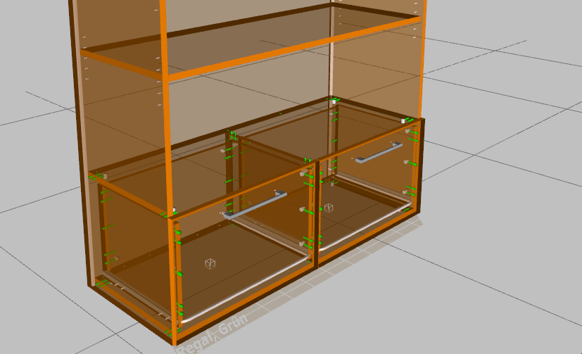
Let's now select suitable excerpts and drag them to our shelf.
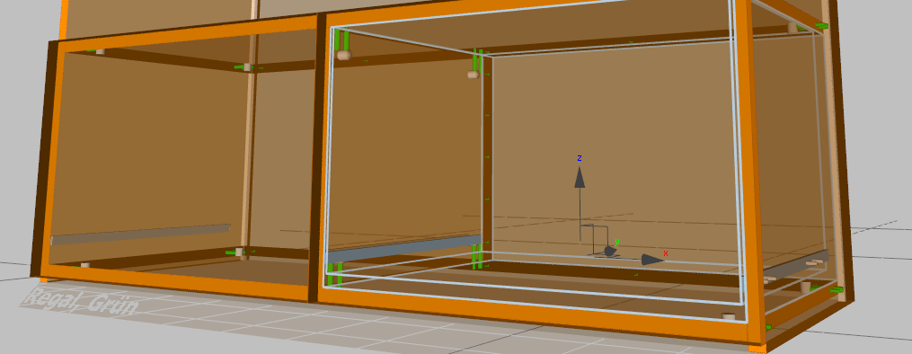
Once the separations have been placed, a light blue frame will appear in the volume. This frame specifies the maximum volume that is now available for drawers.
Now, before choosing the actual drawers, we want to select the handles for the drawers, then we're done with the fittings.
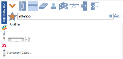
We change the view from slides to handles and enter the article number (or choose a handle).
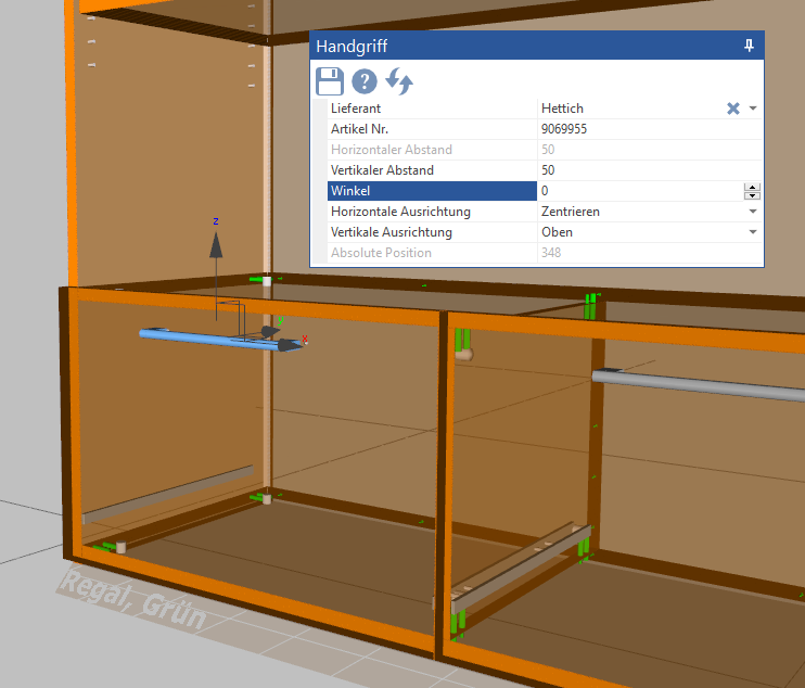
Let's pull the handles in. If the angle is wrong, it can be corrected from 90° to 0°.
The fittings are now complete.
Step 9:
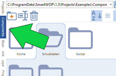
Pull in the drawer components
SmartWOP has some sample components that come with the installation right out of the box. This can be reached through the gallery. Let's click on the Gallery tab, and then on the vertical tab "Components" the included components will be displayed.
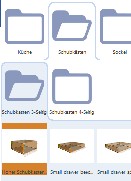
We now select the drawers in the subfolders and the component “Tall drawer, white chipboard” in the drawers.
Then simply pull this component behind both drawer fronts. The component adapts to the design.
Step 10:
materials
Last but not least we want to get the “nice” green color on the closet. To do this, we switch to the Materials tab.
We now select the appropriate surface (example here Pfleiderer Uni decors U046).
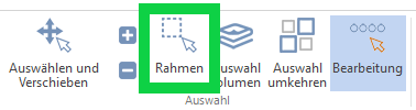
Now we can either use the “Frame” menu item or hold down the Shift key to draw a frame around our shelf and thus select all parts.
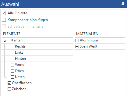
In the selection window we now only select the surfaces.
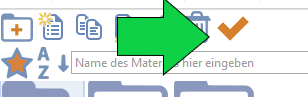
Then we confirm that all surfaces are covered with the selected material by clicking on the orange check mark in the top right.
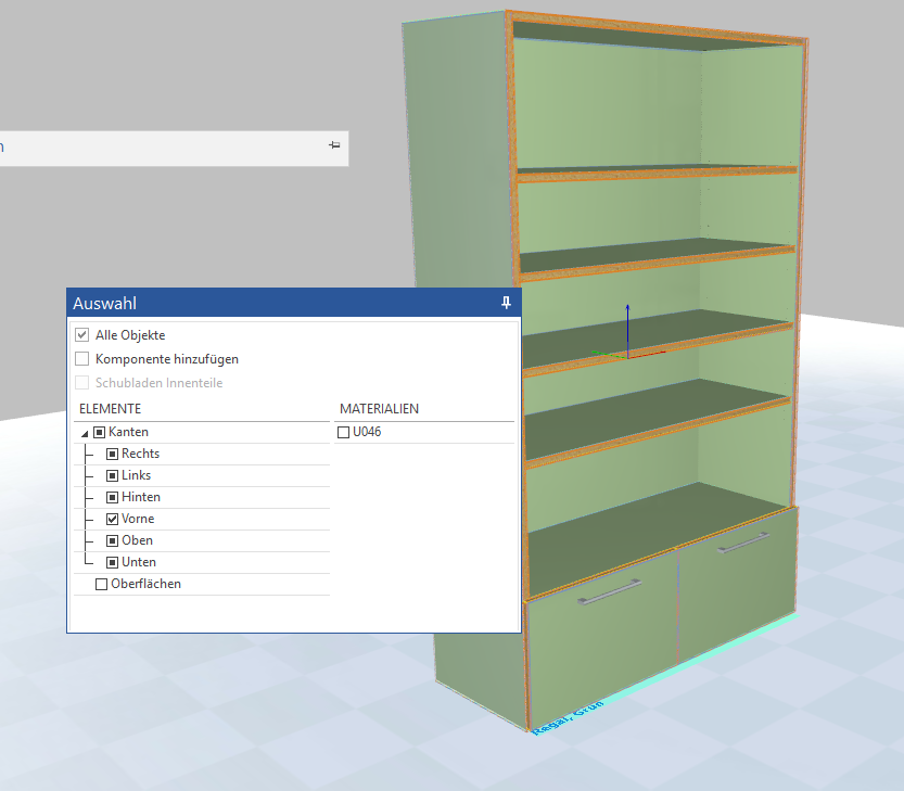
Now all surfaces are adjusted.
Now we will color the edges white. To do this, select the appropriate material in the material folder (example Standard / Span White), draw a frame around the entire piece of furniture and only select the edges. And confirm as before by clicking on the yellow tick.
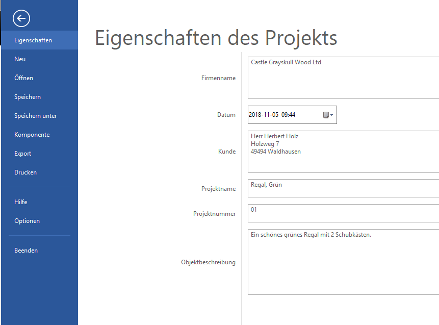
Complete?! Nearly!
Don't forget to enter the customer data.
To do this, click on File in the menu and then Properties.
Complete!
Now we can export to the machine as usual and print our bills of materials.